Independent reference · verified 2026-09-12
Dock Leveler Parts Diagram: 54 Entries Traced to Their Manuals
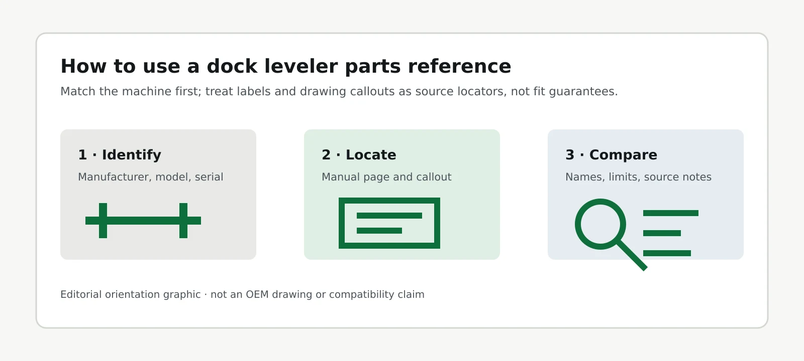
What are the key dock leveler identification findings?
One Poweramp manual uses three names for its platform-lifting cylinder: Platform Cylinder, Hoist Cylinder, and Cylinder, Main Hoist. This dock leveler parts diagram reference preserves their separate page locators instead of treating a diagram name as a replacement identifier. (S2, August 2020, pp. 9, 14 and 43.)
The findings below were checked against the named sources on September 12, 2026; edition dates identify the documents, not the age of a reader’s machine.
- One manual, three names for one cylinder. Poweramp’s LHP hydraulic manual (4111-0012, August 2020) uses Platform Cylinder on p. 9, Hoist Cylinder within the shim-location legend on p. 14, and Cylinder, Main Hoist on p. 43. The p. 14 callout J points to shims under the cylinder, not directly to the cylinder. (S2)
- Five names around the drive-on structure—not five interchangeable parts. The source set uses Platform (Poweramp LMP, December 2018, p. 9), Deck (Blue Giant 038-1083E, Rev. 1.6, August 2026, §10.4), Platform Weldment (Rite-Hite ML-900, June 2015, p. 15), Deck Plate Test (ANSI MH30.1-2015 contents, §5.3), and ramp (Poweramp placard 1751-0875 Rev. D, LMP p. 5). A plate, a complete weldment and the broader ramp description do not establish identical assembly boundaries. (S1; S3; S6; A15)
- One page, two names for one lubrication point. On p. 25 of Poweramp’s December 2018 LMP manual, point C is labeled Lip Link Pivots in the figure legend and Lip banger pivots in the text beneath it. (S1)
- A diagram letter is not a part number. Poweramp’s December 2018 LMP manual says ordering uses part numbers and descriptions, not item numbers, and calls for the model number and/or serial number; drawing item numbers locate components. The same distinction appears in the August 2020 LHP manual. (S1, p. 41; S2, p. 49)
- A mechanical leveler can contain a shock absorber. Poweramp’s December 2018 LMP drawing labels both main lift springs (p. 9, U) and a lip shock absorber (p. 9, Q); its parts table names a gas-shock kit at p. 37, N. A shock-shaped component alone does not identify a hydraulic lifting system. (S1)
- Two separately named props in one drawing; one in the other. The December 2018 LMP overview labels a Platform Maintenance Prop and a Lip Maintenance Prop; the August 2020 LHP overview labels a Maintenance Prop. These are counts of the named props in those particular figures, not a universal count of required support devices. (S1, p. 9, B and L; S2, p. 9, E)
- Both selected Poweramp manuals point modifications back to MH30.1. Their owner-responsibility sections require prior written manufacturer approval and conformity with applicable MH30.1 provisions for modifications. The inspected editions are LMP December 2018 and LHP August 2020. (S1; S2, p. 6)
- Two OSHA standards appear together in the maintenance precautions. The December 2018 LMP and August 2020 LHP manuals reference 29 CFR 1910.146 and 1910.147. Those references do not themselves classify every dock pit as a permit-required confined space. (S1, p. 24; S2, p. 28; R146)
- OSHA’s dockboard definition includes dock levelers. The federal definition at 29 CFR 1910.21(b), checked in 2026, expressly includes them; the ANSI MH30.1-2015 scope directs portable dock-leveling devices to MH30.2. This is a difference in terminology and scope, not proof that one rule overrides another. (R21; A15, §1.2)
- January 17, 2017 is the federal run-off provision’s initial-service cutoff. Section 1910.26(b)(1) addresses dockboards first placed in service on or after that date; paragraph (b)(2) allows no run-off protection where the employer demonstrates there is no run-off hazard. The text does not prescribe one universal side-guard design. (R26; checked 2026)
- About three inches is an industry-paper scenario, not a mandated guard height. LODEM’s undated paper argues that a side guard projecting approximately three inches above a stored pit leveler would create cross-traffic problems. This is the paper’s design argument, not a field measurement or an OSHA-approved exception. (L1, p. 2; checked 2026)
- The selected Poweramp and Blue Giant manuals specify the same minimum lip overlap: 4 in. (102 mm). That minimum appears in Poweramp’s December 2018 LMP and August 2020 LHP examples and Blue Giant’s August 2026 mechanical manual. It is a source-specific operating requirement, not a substitute for the complete unit instructions. (S1, p. 21; S2, p. 25; S6, p. 13)
- Four color-coded main lift springs appear in the LMP table. Poweramp’s December 2018 manual lists blue, red, black and yellow springs with length, outside diameter, wire diameter and coil count. The table’s length heading does not say “free length.” (S1, p. 33)
- A sample serial plate prints a 10-year minimum life expectancy—not a measured lifespan. Blue Giant’s August 2026 manual reproduces decal 038-1082EF for sample model M7008W, with a maximum static distribution load of 30,000 lb (13,607 kg). Those are labels on the illustrated plate, not ratings or observed service life for every Blue Giant leveler. (S6, p. 17)
- This compilation has 54 main entries plus 4 edge-of-dock entries: 58 reference IDs. Its six core manuals represent three manufacturers; one supplemental Blue Giant air-powered manual supplies an additional support term. These are reproducible counts of this reference, not the number of parts in any one machine. (Component index; extension; dataset; compiled 2026)
Byline: Elkhart Dock Door Repair Research
Last verified: September 12, 2026
The drive-on structure has five names in this source set. Building this dock leveler parts diagram reference meant reading the selected manufacturer pages side by side. Poweramp calls it the platform. Blue Giant calls it the deck. Rite-Hite calls its assembly the platform weldment. The historical American National Standard’s contents include a deck-plate test. And the operating placard reproduced beside the Poweramp instructions uses ramp — in the same manual that calls it a platform. The names overlap, but an assembly name and a plate name are not automatically the same replacement item. (S1, pp. 5 and 9; S3, p. 15; S6, p. 21; A15, contents.)
That naming spread is not limited to different manufacturers. In three documented examples below, more than one label appears inside a single manual, including two descriptions of the same lubrication point on one page. The useful result is a traceable vocabulary map, not a claim that every alternative name denotes an identical part. (Naming comparison.)
On this page
What a dock leveler is · Mechanical parts diagram · Hydraulic parts diagram · The full component index · Why one part has several names · Which parts the standard names · Air-powered and edge-of-dock differences · Finding your own manual · Methodology · What this page cannot establish · Indiana enforcement · Attribution details · Dataset files · Questions · Sources
Diagram references: Poweramp LMP mechanical drawing — printed p. 9 · Poweramp LHP hydraulic drawing — printed p. 9. Each opens the manufacturer’s PDF; printed page 9 is PDF viewer page 11 in these two files.
What is a dock leveler, and which three kinds does the standard cover?
A dock leveler provides a bridge between a loading dock and a transport-vehicle bed; the pit-style examples here have a hinged platform and lip. ANSI MH30.1-2015’s published scope identifies three categories: dock-face mounted, fixed, and rail. These are equipment configurations, not three names for the lifting mechanism. (A15, §1.2; S1; S2, p. 9.)
Dock-face mounted units are also called edge-of-dock levelers. The fixed category covers horizontal- and vertical-storing units; the rail category covers fixed and sliding arrangements. Pit-style levelers, represented by the LMP and LHP drawings, are fixed units recessed into a dock pit. The historical scope sends portable dock-leveling devices to MH30.2 rather than treating them as another actuation system. (A15, §1.2.)
Three variables help decide which drawing applies: what lifts the platform, whether the unit is pit-mounted or dock-face mounted, and which manufacturer and model family built it. Springs, hydraulic cylinders and an air bag are the lifting examples in the inspected manuals; edge-of-dock describes mounting, not a fourth lifting technology. (S1; S2; S4; S5, identification pages.)
Two size and capacity examples follow, read from the named manual editions—not represented as current specifications for every unit sold today.
| Specification | LMP (mechanical), December 2018 | LHP (hydraulic), August 2020 |
|---|---|---|
| Widths | 6 ft, 6½ ft, 7 ft | 6 ft, 6½ ft, 7 ft |
| Lengths | 6 ft, 8 ft | 6 ft, 8 ft, 10 ft |
| Capacities (CIR) | 25,000 / 30,000 / 35,000 / 40,000 lb | 25,000 / 35,000 / 40,000 lb |
| Illustrated working range | ±12 in. (305 mm) | ±12 in. (305 mm) |
| Lip hinge pins in cited parts table | 1 | 2 |
| Rear hinge pins in cited parts table | 3 | 3 |
CIR stands for Comparative Industry Rating, the manufacturer’s term. The operating-range figures carry a manufacturer qualification that service height may vary with design specifications. The pin quantities belong to the specific parts-table assemblies, not every model from either manufacturer.
Source: Poweramp LMP 4111-0013, December 2018, pp. 8, 21, 35 and 37; LHP 4111-0012, August 2020, pp. 8, 25 and 41. Checked September 12, 2026.
What does the mechanical dock leveler parts diagram label?
The Poweramp LMP mechanical dock leveler parts diagram labels 19 positions, using letters A through U but omitting I and O. Its springs raise the platform, while the ratchet hold-down restrains the platform against that upward spring force; it is not a prop supporting the platform from underneath. The legend below follows the December 2018 identification drawing, not a universal mechanical-leveler layout. (S1, p. 9, Figure 4, and hold-down/operating material.)
Mechanical drawing reference: View the manufacturer’s labeled LMP diagram — Figure 4, printed p. 9 / PDF page 11.
Drawing description: Poweramp LMP pit-style mechanical arrangement, with the lip, platform, lift and hold-down components, safety-leg controls, and separately named platform and lip props. The drawing is hosted by the manufacturer; the searchable legend below is this page’s reference table. No original illustration is claimed in this release.
| Callout | Manufacturer’s label | What it is, in plain words |
|---|---|---|
| A | Lip | The hinged plate that extends onto the trailer floor. |
| B | Lip Maintenance Prop | A separate lip-support device for authorized service; not the platform prop at L. |
| C | Platform | The drive-on structure. |
| D | Lip Link | The chain/link element shown in the lip-actuation path; not a label for every part of the lip-banger assembly. |
| E | Lip Assist Rod | Rod in the lip-assist linkage. |
| F | Platform Release Ring | The release control associated with the hold-down mechanism. |
| G | Ratchet Pawl | The catch that engages the ratchet bar. |
| H | Ratchet Bar | The toothed member engaged by the pawl to restrain upward platform movement. |
| J | Pawl Spring | The spring associated with pawl engagement. |
| K | Main Frame | The base structure in the pit. |
| L | Platform Maintenance Prop | The platform-support device for authorized service. |
| M | Hold-Down Mechanism | The assembly containing the ratchet bar and pawl. |
| N | Safety Leg | A safety-leg component, separate from the maintenance prop. |
| P | Lip (Snubber) Spring | A spring in the lip-control path, not a snubbing chain. |
| Q | Lip Shock Absorber | The lip-related damper; the parts list identifies a gas-shock kit. |
| R | Safety Leg Linkage | Linkage associated with the safety-leg control. |
| S | Safety Leg Pull Ring | The safety-leg control ring, separate from the platform release ring. |
| T | Lift Arm Assembly | The arm assembly associated with the main lifting springs. |
| U | Lift (Main) Spring Assembly | The springs that raise the platform. |
Source: Poweramp LMP 4111-0013, December 2018, p. 9, Figure 4; related parts and naming checks at pp. 25, 31, 32, 35 and 37. Plain-language descriptions are editorial explanations, not quoted operating instructions. Checked September 12, 2026.
Identifying a main lift spring by color
The LMP manual’s main-lift-spring table identifies four springs by color, with dimensions for each. This is identification data for the named manual, not permission to select a spring from color alone: the same parts material calls for unit-identifying information. Main springs hold stored energy; maintenance and adjustment belong to trained, authorized personnel using the manufacturer’s precautions. (S1, pp. 24, 33 and 41.)
| Part number | Color | Length (A), as labeled | Outside diameter | Wire diameter | Coils |
|---|---|---|---|---|---|
| DOTH-2570 | Blue | 20 in. (508 mm) | 3.468 in. (88 mm) | 0.406 in. (10 mm) | 38 |
| DOTH-2574 | Red | 21 in. (533 mm) | 4.750 in. (121 mm) | 0.531 in. (13 mm) | 26 |
| DOTH-2576 | Black | 23 in. (584 mm) | 3.875 in. (98 mm) | 0.500 in. (12 mm, as printed) | 37 |
| DOTH-2578 | Yellow | 23 in. (584 mm) | 4.700 in. (119 mm) | 0.594 in. (15 mm) | 30 |
Source: Poweramp LMP 4111-0013, December 2018, p. 33. Dimensions and rounded metric equivalents are reproduced as printed; this table does not call Length (A) a free-length measurement. Checked September 12, 2026.
Published-unit discrepancy: the black spring’s wire diameter is printed as 0.500 in. (12 mm). Using NIST’s exact conversion of 25.4 mm per inch, 0.500 in. converts to 12.7 mm. Both the OEM’s printed value and the arithmetic are left visible; this reference does not choose a replacement dimension or infer a tolerance from that discrepancy. (S1, p. 33; N1; conversion checked September 12, 2026.)
What does the hydraulic dock leveler parts diagram label?
The Poweramp LHP hydraulic dock leveler parts diagram labels 10 positions, using letters A through K but omitting I. This particular layout uses a platform cylinder and a separate lip cylinder, supplied by a motor/pump/reservoir powerpack. It is the August 2020 LHP arrangement, not a universal cylinder-count rule for hydraulic levelers. (S2, p. 9, Figure 4.)
Hydraulic drawing reference: View the manufacturer’s labeled LHP diagram — Figure 4, printed p. 9 / PDF page 11.
Drawing description: Poweramp LHP pit-style hydraulic arrangement, showing the lip, platform, two separately labeled cylinders, powerpack, maintenance prop, main frame, lip keepers, toe guards and control box. This is a link to the manufacturer’s drawing, not a newly drawn schematic or a replacement-parts guarantee.
| Callout | Manufacturer’s label | What it is, in plain words |
|---|---|---|
| A | Lip | The hinged plate that extends onto the trailer floor. |
| B | Platform | The drive-on structure. |
| C | Lip Cylinder | The cylinder associated with lip positioning. |
| D | Powerpack (Motor/Pump/Reservoir) | One assembly label covering the electric motor, pump and fluid reservoir. |
| E | Maintenance Prop | The platform-support device identified in this drawing. |
| F | Platform Cylinder | The platform-lifting cylinder; elsewhere called the hoist or main hoist cylinder. |
| G | Main Frame | The base structure in the pit. |
| H | Lip Keepers | The supports receiving the folded lip in the stored position. |
| J | Full Range Toe Guards | The side-guard assemblies identified by the manufacturer. |
| K | Control Box | The control enclosure; the manual says its appearance varies with options. |
Source: Poweramp LHP 4111-0012, August 2020, p. 9, Figure 4. Plain-language descriptions are editorial explanations; additional naming locators are pp. 14 and 43. Checked September 12, 2026.
The two cylinders, with published dimensions
The two cylinders are different entries, even though the manual gives the platform-lifting cylinder three names. Its parts table distinguishes them by description and dimensions. Those dimensions identify the listed LHP examples; they do not establish the correct replacement for a different size, serial number or revision. (S2, pp. 9, 14, 43 and 49.)
| Parts-table item | Manufacturer’s label | Part number | Published specification |
|---|---|---|---|
| A | Cylinder, Lip | DOTH-2852 | 2 in. bore × 6 in. stroke |
| B | Cylinder, Main Hoist | 0521-0211 | 2.5 in. bore × 14 in. stroke |
| D | Hyd Hose, 3/8 in. 100R1 | 9904-0087 | 33.00 in. long |
| E | Hyd Hose, 3/8 in. 100R1 | 9904-0115 | 72.00 in. long, #6 JICM |
| F | Velocity Fuse | DOTH-2771 | 3 GPM |
| H | Powerpack | DOTH-2854 / DOTH-2855 | 115/230 V 1-phase / 230/460 V 3-phase, respectively |
Source: Poweramp LHP 4111-0012, August 2020, p. 43. Letters in this parts table are not the same identification system as the p. 9 overview drawing. Checked September 12, 2026.
The velocity fuse and a mechanical safety leg are distinct components, not replacement synonyms. The 2015 standard’s public contents include the heading Uncontrolled Drop Restrictors at §4.8; this reference groups those component topics under that heading without claiming to have read or applied the full clause. A patent’s discussion of a load-sensing cylinder describes another mechanism, not another name for the LHP’s velocity fuse. (S2, p. 43; S1, p. 9; A15, contents; P3, background.)
What is in the full dock leveler component index?
The main index contains 54 selected component and reference entries, grouped broadly by structure, lip mechanism, lifting and control systems, and protective or identification items. Each row records manufacturer wording and a manual locator, with separate notes where a label names a subpart, kit or related—but different—device. Four edge-of-dock entries extend the reference to 58 IDs in Table 9.
Locators read as source, printed page, callout or item. For example, S1 p. 9 C means the Poweramp LMP manual, printed page 9, callout C. The downloadable evidence also records the one-based PDF viewer page, so a reader does not have to guess whether the cover was included in the count.
A missing mapping means we did not map that component in that source. It does not mean the part is absent from that equipment. ★ means the listed primary-source page was checked directly; the table’s grouping and explanations remain editorial comparisons, not compatibility findings. The source editions are listed in Table 10.
| ID | Component / reference entry | Manufacturer’s labels, with locator | Other names and mapping boundaries | Design examples |
|---|---|---|---|---|
| 01 ★ | Platform | Platform (S1 p. 9, C); Platform (S2 p. 9, B); Platform Weldment (S3 p. 15, item 2); Deck (S6 p. 21, §10.4) | Deck Plate Test (A15, contents, §5.3); ramp (S1, p. 5 placard). These names concern the drive-on structure at different levels: a weldment is not merely its plate. Historical heading: 5.3 Deck Plate Test (contents heading only); see Table 8. | Mechanical / hydraulic examples |
| 02 ★ | Lip | Lip (S1 p. 9, A); Lip (S2 p. 9, A); Lip Weldment (S3 p. 15, item 3) | extension plate, or lip (P2); lip plate (P1). Patent terminology does not establish replacement equivalence. | Mechanical / hydraulic examples |
| 03 ★ | Lip hinge pin | Pin, Lip Hinge (S1 p. 37, E); Pin, Lip Hinge (S2 p. 41, C); Lip Shaft (S6 p. 21, §10.6) | lip hinge pin (P1). Part dimensions and quantities remain model-specific. | Pit examples |
| 04 ★ | Rear hinge pin | Pin, Hinge, Rear (S1 p. 35, M); Rear Hinge Pin (S2 p. 41, F) | hinge pin 32 (P1). Keep separate from the lip hinge pin. | Pit examples |
| 05 ★ | Main frame | Main Frame (S1 p. 9, K); Main Frame (S2 p. 9, G); Frame, LH (S2 p. 41, G); Frame (S6 p. 20, item 1) | leveler frame (P2). Category comparison, not interchangeable frame assemblies. | Mechanical / hydraulic examples |
| 06 ★ | Front header plate | Platform Header (S1 p. 24, D); Header (S2 p. 28, D) | front bar 34 is a related term in P1. The patent term is not a verified OEM replacement synonym. | Pit examples |
| 07 ★ | Platform joists | Platform Joists (S2 p. 18, A); side joists (S1 p. 13, installation text) | Structural members; not a parts-ordering specification. | Pit examples |
| 08 ★ | Rear hinge frame angle | Rear Hinge Frame Angle (S1 p. 14, H); Rear Hinge Frame Angle (S2 p. 14, H) | — | Pit examples |
| 09 ★ | Rear pit curb angle | Rear Pit Curb Angle (S1 p. 14, F); Rear Pit Curb Angle (S2 p. 14, F) | A pit-interface item; the index is not limited to parts shipped with the machine. | Pit examples |
| 10 ★ | Side pit curb angle | Side Pit Curb Angle (S1 p. 16, C); Side Pit Curb Angle (S2 p. 16, C) | Keep separate from the rear pit curb angle. | Pit examples |
| 11 ★ | Shim stack | Shim Stack (S1 p. 14, M); Shim Stack (S2 p. 14, M) | Identification only, not a shimming or installation procedure. | Pit examples |
| 12 ★ | Lifting bracket | Lifting Bracket (S1 p. 13, A); Lifting Bracket (S2 p. 13, A) | Shipping/installation drawing reference, not a lifting instruction. Historical heading: 4.5 Lifting Aides (contents heading; editorial topic map); see Table 8. | Pit examples |
| 13 ★ | Lip keeper | Keeper, Lip (S1 p. 35, S); Lip Keepers (S2 p. 9, H); Lip Keeper Weldment (S3 p. 17, item 48); Lip Keeper (S6 p. 20, item 25) | lip keepers (P1). Not a lip latch: the AP legend separately identifies Lip Latch Assembly at D and Lip Keepers at H. | Mechanical / hydraulic examples |
| 14 ★ | Lip assist rod | Lip Assist Rod (S1 p. 9, E); Lip Assist Rod (S1 p. 37, K); Rod, Lip Assist (S3 p. 15, item 10) | Names are compared; size and fit are not. | Mechanical examples |
| 15 ★ | Lip assist spring | Spring, Lip Assist, Standard (Gray); Heavy Duty (Green) (S1 p. 37, L); Lip Assist Spring (S6 p. 20, item 38) | Blue Giant lists 1003131 as Lip Assist Spring; 1002455 is the separate Lip Activating Spring at item 46 (S6, p. 20). Do not merge the two Blue Giant spring entries. | Mechanical examples |
| 16 ★ | Lip linkage / lip banger | Lip Link Pivots (S1 p. 25, legend C); Lip banger pivots (S1 p. 25, text item C); Lip Banger Assembly, Neutron (S1 p. 37, P) | The lubrication-point names concern pivots; the parts table names the assembly. Do not merge the separate chain in entry 17. | Mechanical example |
| 17 ★ | Lip assist link chain | Lip Link (S1 p. 9, D); Chain, Lip Assist Link (S1 p. 35, D); lip assist chain (S1 p. 31, troubleshooting text) | The overview arrow and parts drawing identify the chain/link path, not the complete lip-banger assembly. | Mechanical example |
| 18 ★ | Lip snubber spring | Lip (Snubber) Spring (S1 p. 9, P); Spring, Snubber (S1 p. 35, B) | Snubbing Chain Assembly is a separate chain entry in S3, p. 15 item 19. A snubber spring and a snubbing chain are not the same component. | Mechanical example |
| 19 ★ | Lip shock absorber | Lip Shock Absorber (S1 p. 9, Q); Kit, Gas Shock w/Hardware (S1 p. 37, N); gas shock (S1 p. 31, troubleshooting text) | The kit includes hardware; the names do not prove all similarly shaped parts fit. | Mechanical example |
| 20 ★ | Lip stop bolt | Stop Bolt (S1 p. 28, C) | — | Mechanical example |
| 21 ★ | Below dock control assembly | Below Dock Control Assembly (S1 p. 37, C); Below Dock Chain Assembly (S1 p. 37, F) | Two separately listed assemblies in the same control path, not two names for one orderable part. | Mechanical example |
| 22 ★ | Lip cylinder | Lip Cylinder (S2 p. 9, C); Cylinder, Lip (S2 p. 43, A) | Separate from the platform/main hoist cylinder. | Hydraulic example |
| 23 ★ | Main lift spring | Lift (Main) Spring Assembly (S1 p. 9, U); Spring, Lift (S1 p. 35, K); Main Spring (S6 p. 20, item 31) | Keep separate from lip-assist and pawl springs. | Mechanical examples |
| 24 ★ | Lift arm | Lift Arm Assembly (S1 p. 9, T); Lift Arm, Short; Lift Arm, Long (S1 p. 35, G); Upper Arm Weldment (S6 p. 20, item 33); Lower Arm Weldment (S6 p. 20, item 47) | LMP lists 25 in. and 27 in. lift-arm variants. Upper and lower Blue Giant arm weldments are separate items; functional grouping is not one-to-one equivalence. | Mechanical examples |
| 25 ★ | Lift arm caster | Caster Assembly, 4 in. OD (S1 p. 35, J); Lift Arm Roller Bushing (S1 p. 25, E) | The roller bushing is a related subcomponent/lubrication location, not another name for the complete caster. | Mechanical example |
| 26 ★ | Hold-down mechanism | Hold-Down Mechanism (S1 p. 9, M); Hold Down Assembly Complete (S1 p. 32, parts-table assembly heading); Ratchet Hold-Down Assembly (S6 p. 24, assembly heading); Ramp Control Assembly (S3 p. 15, item 24) | Function-based comparison of different assemblies; not a replacement cross-reference. | Mechanical examples |
| 27 ★ | Ratchet bar | Ratchet Bar (S1 p. 9, H); Ratchet Bar and Pawl Assembly (S1 p. 32, A); Ratchet Bar (S6 p. 24, item 1) | LMP p. 32 A includes the pawl; it is not a bar-only listing. | Mechanical examples |
| 28 ★ | Ratchet pawl | Ratchet Pawl (S1 p. 9, G); Pawl Assembly (S6 p. 24, item 6) | Assembly contents depend on the manufacturer. | Mechanical examples |
| 29 ★ | Pawl spring | Pawl Spring (S1 p. 9, J); Pawl Spring (S1 p. 32, D); Spring, Retainer Pawl (S6 p. 24, item 7) | — | Mechanical examples |
| 30 ★ | Release arm spring | Spring, Release Arm (S1 p. 32, C) | — | Mechanical example |
| 31 ★ | Platform release ring | Platform Release Ring (S1 p. 9, F); Ring, Chain (S1 p. 35, P); Pull Ring (S6 p. 20, item 28) | Not the separate safety-leg pull ring in entry 49. | Mechanical examples |
| 32 ★ | Hold-down release chain | Chain, Hold-Down Release (S1 p. 35, Q); Ratchet Chain Assembly (S6 p. 20, item 27) | Release-function comparison; assembly lengths and contents not normalized. | Mechanical examples |
| 33 ★ | Release chain roller | Roller, Release Chain (S1 p. 35, U) | — | Mechanical example |
| 34 ★ | Secondary pulley | Secondary Pulley Assembly (S1 p. 35, AD) | — | Mechanical example |
| 35 ★ | Platform cylinder | Platform Cylinder (S2 p. 9, F); Shims Location (Under Hoist Cylinder) (S2 p. 14, J, shim-location legend); Cylinder, Main Hoist (S2 p. 43, B) | main cylinder 45 (P1). On p. 14, J identifies the shims under the cylinder; the cylinder name is embedded in that legend. | Hydraulic example |
| 36 ★ | Powerpack | Powerpack (Motor/Pump/Reservoir) (S2 p. 9, D); Powerpack (S2 p. 43, H) | power unit 60 (P1). An assembly of motor, pump and reservoir, not a name for only one of those parts. | Hydraulic example |
| 37 ★ | Hydraulic hose | Hyd Hose, 3/8 in. 100R1 (S2 p. 43, D); Hyd Hose, 3/8 in. 100R1 (S2 p. 43, E) | The two listed lengths and their fittings remain distinct. | Hydraulic example |
| 38 ★ | Fluid reservoir | Fluid Reservoir (S2 p. 32, C); Reservoir (S2 p. 31, E) | — | Hydraulic example |
| 39 ★ | Breather cap | Breather Cap (S2 p. 31, F); Breather, Vent Plug (S2 p. 43, C) | The parts-table specification, not the short name alone, identifies the replacement. | Hydraulic example |
| 40 ★ | Sequence valve | Sequence Valve (S2 p. 32, A); Sequence Valve (S2 p. 33, A) | No adjustment settings or procedure are supplied. | Hydraulic example |
| 41 ★ | Pressure relief valve | Pressure Relief Valve (RV1) (S2 p. 32, B) | No adjustment settings or procedure are supplied. | Hydraulic example |
| 42 ★ | Air bag | Air Bag (S4 p. 9, J) | Distinct lifting element; not a hydraulic cylinder. | AP air-powered example |
| 43 ★ | Blower motor | Blower Motor (S4 p. 9, M) | Not the electric motor inside a hydraulic powerpack. | AP air-powered example |
| 44 ★ | Platform maintenance prop | Platform Maintenance Prop (S1 p. 9, L); Prop, Maintenance (S1 p. 35, R); Maintenance Prop (S2 p. 9, E); Maintenance Prop Rod (S2 p. 41, H); Maintenance Support (S3 p. 17, item 37); Dock Strut (S6 p. 9, support illustration); Maintenance Strut (S7 p. 13, support illustration) | These support-related names do not establish identical support arrangements or compatible replacements. Historical heading: 4.7 Maintenance Device (contents heading; editorial topic map); see Table 8. | Selected pit examples |
| 45 ★ | Lip maintenance prop | Lip Maintenance Prop (S1 p. 9, B); Assembly, Lip Prop (S1 p. 37, M) | separate lip support Separate from the platform prop; no installation or use sequence is supplied. Historical heading: 4.7 Maintenance Device (contents heading; editorial topic map); see Table 8. | LMP mechanical example |
| 46 ★ | Prop pin and clip | Prop Pin & Clip (S1 p. 35, H); Prop Pin & Clip (S2 p. 41, J) | Part number 9201-0006 in both cited tables. No broader interchangeability is established. | LMP / LHP examples |
| 47 ★ | Safety leg | Safety Leg (S1 p. 9, N); Safety Leg (S3 p. 15, item 31); Fall Safe Weldment (S6 p. 20, item 52) | Blue Giant item 52 is part 2000403. Maintenance supports and safety legs have distinct identities. Historical heading: 4.8 Uncontrolled Drop Restrictors (contents heading; editorial topic map); see Table 8. | Mechanical examples |
| 48 ★ | Safety leg linkage | Safety Leg Linkage (S1 p. 9, R) | — | Mechanical example |
| 49 ★ | Safety leg pull ring | Safety Leg Pull Ring (S1 p. 9, S); Safety Leg Chain Pull Ring (S1 p. 18, A) | Not the platform release ring. | Mechanical example |
| 50 ★ | Velocity fuse | Velocity Fuse (S2 p. 43, F) | The cited parts table specifies 3 GPM. A load-sensing cylinder discussed in patent literature is a different mechanism, not a verified synonym. Historical heading: 4.8 Uncontrolled Drop Restrictors (contents heading; editorial topic map); see Table 8. | Hydraulic example |
| 51 ★ | Toe guards | Toe Guard Kit, Sliding (S1 p. 39, A); Toe Guard, Middle (S1 p. 39, B); Toe Guard, Lower (S1 p. 39, C); Full Range Toe Guards (S2 p. 9, J); Toe Guards (S6 p. 25, §12.0) | Guard configuration depends on the model and size. Historical heading: 4.4.1 Toe Guards (contents heading; editorial topic map); see Table 8. | Selected pit examples |
| 52 ★ | Weather seal | Brush Kit; Rubber Kit (S1 p. 38, A); Rear Brush Weather Seal (S1 p. 38, E); Brush Kit; Rubber Kit (S2 p. 44, A); Rear Brush Weather Seal (S2 p. 44, E) | Weather-seal names are not substituted for toe guards or safety skirts. | Pit examples |
| 53 ★ | Control box | Control Box (S2 p. 9, K); Danfoss Control Box (S2 p. 38, wiring-page heading); Control Panel (S2 p. 20, B); Control Box (S4 p. 9, Q) | The TLC24 described in S6, p. 28 is a separate traffic-light controller. Do not treat a traffic-light controller as an interchangeable leveler-motion control box. Historical heading: 4.6 Controls (contents heading; editorial topic map); see Table 8. | LHP / AP powered examples |
| 54 ★ | Model/serial number decal | Leveler model/serial number decal (S1 p. 41, A); Leveler model/serial number decal (S2 p. 49, A); Serial Plate Decal (S6 p. 17, decal 038-1082EF) | Sample decal illustrations are not the rating plate of the reader’s machine. Historical heading: 4.9.1 Manufacturer’s Nameplate (contents heading; editorial topic map); see Table 8. | Selected pit examples |
Source: Primary component evidence: Poweramp LMP S1, December 2018; Poweramp LHP S2, August 2020; Rite-Hite ML-900 S3, June 2015; Poweramp AP S4, September 2020; Blue Giant mechanical S6, August 2026. Supplemental support terminology: Blue Giant air-powered S7, August 2026, p. 13. Historical headings: A15, contents only. Patent vocabulary: P1, P2 and P3, original patent text. The DLM extension sourced to S5 is in Table 9. Checked September 12, 2026.
Dataset files: component evidence CSV · complete reference JSON. The CSV is one row per component/source observation, not one row per reference ID; the JSON includes the grouped index, source register and disclosed gaps. Attribution details are recorded below.
Why does one component end up with several names?
A diagram label, a parts-table assembly name and an operating term do different jobs. In the inspected sources, that distinction produces overlapping names within the same manual as well as between manufacturers. It does not establish that similarly named parts have the same dimensions, contents or replacement fit. (Table 7; S1; S2; S3; S6.)
A useful way to read the naming spread is by the document’s job. The historical standard’s contents use broad terms such as maintenance device and uncontrolled drop restrictors. The manufacturer manuals use assembly names such as lip banger and powerpack. Patent descriptions use terms such as extension plate and leveler frame. Parts tables distinguish a complete assembly from the rod, spring, pin or hardware kit supplied separately. That is an editorial reading of these documents, not a surveyed explanation of the entire industry. (A15, contents; S1, pp. 35 and 37; S2, p. 43; P1; P2.)
The part that stands out is how often a single document carries more than one name around the same item. Below are the three examples that can be checked at their source locations.
| Component or assembly | First label, with locator | Second label, with locator | Third label, with locator |
|---|---|---|---|
| The platform-lifting hydraulic cylinder | Platform Cylinder (S2 p. 9, F) | Hoist Cylinder, within “Shims Location (Under Hoist Cylinder)” (S2 p. 14, J) | Cylinder, Main Hoist (S2 p. 43, B) |
| The lip linkage and its pivots | Lip Link Pivots (S1 p. 25, legend C) | Lip banger pivots (S1 p. 25, text C) | Lip Banger Assembly, Neutron (S1 p. 37, P) |
| The lip damper | Lip Shock Absorber (S1 p. 9, Q) | Kit, Gas Shock w/Hardware (S1 p. 37, N) | gas shock (S1 p. 31, troubleshooting text) |
Source: Poweramp LHP 4111-0012, August 2020, pp. 9, 14 and 43; Poweramp LMP 4111-0013, December 2018, pp. 9, 25, 31 and 37. Checked September 12, 2026.
The second row is the sharpest of the three: the figure legend and the accompanying text sit on the same printed page and use different words for point C. The third column then names the assembly rather than the lubrication point. Likewise, a shock kit includes hardware, and a shim-location legend is not a direct cylinder callout. Those boundaries stay visible instead of being flattened into a list of supposedly interchangeable synonyms.
A diagram letter is not a part number
This is the single most practical distinction on the page, and it comes straight from the manufacturer. Poweramp’s customer-information pages distinguish orderable part numbers and descriptions from item numbers used to locate a position in a drawing. They ask for the model number and/or serial number. A drawing letter by itself is not an orderable replacement identifier. (S1, p. 41; S2, p. 49.)
The LHP diagrams show why that matters even before a replacement is considered: C means Lip Cylinder in the overview on p. 9, but the parts table on p. 43 uses C for Breather, Vent Plug. A letter only makes sense together with its drawing and page. (S2, pp. 9 and 43.)
Which components do the historical standard and OSHA actually name?
The publicly accessible ANSI MH30.1-2015 contents list eight component- or device-related headings selected in Table 8. This page verifies those headings and numbers, not the full requirements beneath them. OSHA’s separate dockboard definition and run-off provision are quoted by section and discussed independently below. (A15, contents; R21; R26.)
Most of this index’s detail comes from manufacturers’ figures and parts tables, not from the historical standard’s contents. The mapping below is an editorial route from a component topic to a heading. It is not proof that a particular unit or replacement part complies with the standard.
| Historical clause | Published heading | Related index entries / boundary |
|---|---|---|
| 4.4.1 | Toe Guards | 51 — Heading-to-topic comparison; not a finding of compliance. |
| 4.4.2 | Run-Off Guards | — No guard part is mapped from the selected pit-leveler drawings; absence from this index is not proof that none exist. |
| 4.5 | Lifting Aides | 12 — Installation-bracket topic; the full clause was not inspected. |
| 4.6 | Controls | 53 — Control-related topic; no functional equivalence across controllers is implied. |
| 4.7 | Maintenance Device | 44, 45 — Support-related topic; not an approval of a support arrangement. |
| 4.8 | Uncontrolled Drop Restrictors | 47, 50 — Distinct mechanical and hydraulic mechanisms are kept separate. |
| 4.9.1 | Manufacturer’s Nameplate | 54 — Identification-plate topic. |
| 4.9.2 | Warning Labels | — Warning decals are discussed separately rather than counted as individual index entries. |
Source: ANSI MH30.1-2015 public preview, contents page vi, headings 4.4.1–4.9.2. The preview does not expose the full text of those clauses; row mappings are editorial. Checked September 12, 2026.
The preview also lists Deck Plate Test at §5.3. The older 2007 preview lists that test at §3.2, illustrating why clause numbers must travel with the edition. ANSI’s catalog lists the 2022 standard as a revision of the 2015 edition; the full 2022 text was not reviewed for this page. (A15; A07, contents; A22.)
The manuals’ reference to a standard is a separate, directly readable obligation in their owner-responsibility sections. Both inspected Poweramp manuals require prior written manufacturer approval for modifications and conformity with applicable MH30.1 provisions. This page does not turn the historical contents headings into a current certification checklist. (S1; S2, p. 6.)
The run-off guard question
One heading in Table 8 has no component mapped from the selected pit-leveler drawings: run-off guards. That gap in this selected index is not evidence that no pit leveler can be fitted with a guard. The relevant issue is how the broad federal dockboard definition interacts with different equipment designs.
OSHA defines dockboard at 29 CFR 1910.21(b) broadly enough to include bridge plates, dock plates and dock levelers. The ANSI MH30.1-2015 scope directs portable dock-leveling devices to MH30.2, so the industry vocabulary is not identical to the regulation’s umbrella term. Neither vocabulary changes the wording of the federal requirement. (R21; A15, §1.2.)
Section 1910.26(b)(1) requires dockboards placed into initial service on or after January 17, 2017 to be designed, constructed and maintained to prevent transfer vehicles running off the edge. It states a protective outcome, not a single mandatory side-guard configuration. Paragraph (b)(2) allows dockboards without run-off protection where the employer demonstrates that there is no hazard of transfer vehicles running off the edge. (R26, paragraphs (b)(1)–(2).)
LODEM, the Loading Dock Equipment Manufacturers industry group of MHI, published a paper discussing that interaction. The paper says run-off guards are typically fitted to dockboards and typically not fitted to pit-style levelers. Its argument is that a guard projecting roughly three inches above a stored, flush leveler could create a cross-traffic trip hazard and interfere with forklift wheels or tines. It also argues that pit walls and door jambs can provide run-off protection in the arrangement it discusses. These are the industry paper’s positions, not findings made by OSHA about every dock. (L1, pp. 1–3.)
The regulation’s exception is real, but an industry position paper does not establish that a particular workplace qualifies. What demonstrates the absence of a run-off hazard is a facility-specific compliance question for the employer and the enforcing agency, not something a component reference can decide. (R26, paragraph (b)(2).)
Source: Federal text: 29 CFR 1910.21(b) and 29 CFR 1910.26, eCFR. Industry position: LODEM’s undated compliance-considerations paper. Checked September 12, 2026.
Where do air-powered and edge-of-dock levelers differ?
The AP air-powered arrangement and the DLM dock-face-mounted arrangements do not match the LMP or LHP figures. The AP component legend identifies an air bag and blower motor, while the DLM legend identifies a center plate and model-specific hook or lever. These are the named examples, not a rule that every edge-of-dock unit is hand-operated. (S4; S5, p. 9.)
Air-powered describes a lifting system; edge-of-dock describes where the equipment is mounted. The DLM DL/NL/TS examples are dock-face mounted rather than pit-mounted, and their identification drawing assigns the lifting hook to DL and the lifting lever to NL/TS. No mounting procedure or general claim about all edge-of-dock capacity or travel ranges is inferred here. (S5, p. 9; A15, scope.)
| ID | Component / reference entry | Manufacturer’s label, with locator | Design boundary |
|---|---|---|---|
| 42 ★ | Air bag | Air Bag (S4 p. 9, J) | Distinct lifting element; not a hydraulic cylinder. |
| 43 ★ | Blower motor | Blower Motor (S4 p. 9, M) | Not the electric motor inside a hydraulic powerpack. |
| 53 ★ | Control box | Control Box (S4 p. 9, Q) | The AP manual qualifies appearance by options; not unique to air-powered equipment. |
| 55 ★ | Center plate | Center Plate (S5 p. 9, B) | Related to the platform concept, but not a pit-platform replacement term. |
| 56 ★ | Lifting hook / lifting lever | Lifting Hook (DL only) (S5 p. 9, D); Lifting Lever (NL/TS only) (S5 p. 9, E) | One reference entry covers two model-specific operating devices; they are not one interchangeable part. |
| 57 ★ | Extend link arm | Extend Link Arm (NL/TS only) (S5 p. 9, F) | The legend limits this callout to NL and TS. |
| 58 ★ | Bumper blocks | Bumper Blocks (S5 p. 9, J) | Listed with the edge-of-dock assembly; no general mounting or replacement-fit claim. |
Source: Poweramp AP 4111-0009, September 2020, p. 9; DLM DL/NL/TS 4111-0025, February 2019, p. 9, Figure 4. DLM is the brand named on the latter document, although the file is hosted on Poweramp’s domain; both documents identify Systems, LLC. Checked September 12, 2026.
Rows 55–58 extend the main index; they are not hidden inside its 54-entry count. Rows 42, 43 and 53 are repeated here for design comparison and are counted only once in the dataset. The result is 58 distinct reference IDs, including assemblies, individual parts and installation-interface items—not 58 individual parts in one machine.
How do you find the drawing that matches your machine?
The relevant replacement drawing is the one matched to the actual manufacturer, model and serial identification, not merely a similar-looking leveler. Poweramp’s customer-information pages specifically call for a model number and/or serial number when ordering parts. The edition date then identifies exactly which document this reference used; it does not independently prove replacement fit. (S1, p. 41; S2, p. 49.)
The Poweramp LMP and LHP customer-information pages place the model/serial decal on the left platform joist near the front, or lip end, of the leveler. That is a documentation locator, not an instruction to enter the pit or reach beneath equipment. The same manuals’ maintenance precautions address support and hazardous-energy controls, and cite the confined-space and lockout/tagout rules. Any access needed to inspect a concealed plate belongs to the workplace’s authorized procedures, not this naming guide. (S1, pp. 24 and 41; S2, pp. 28 and 49.)
| ID | Manufacturer | Brand and model family | Manual number | Edition inspected |
|---|---|---|---|---|
| S1 | Systems, LLC | Poweramp LMP — mechanical pit | 4111-0013 | December 2018 |
| S2 | Systems, LLC | Poweramp LHP — hydraulic pit | 4111-0012 | August 2020 |
| S3 | Rite-Hite | Genisys ML-900 — mechanical pit | 1212 | June 2015 |
| S4 | Systems, LLC | Poweramp AP — air-powered pit | 4111-0009 | September 2020 |
| S5 | Systems, LLC | DLM DL / NL / TS — edge-of-dock | 4111-0025 | February 2019 |
| S6 | Blue Giant Equipment Corporation | Blue Giant mechanical dock leveler | 038-1083E | Revision 1.6, August 6, 2026 |
Source: The six manufacturer-authored manuals linked by source ID in the table; edition identifiers were checked in the documents themselves. Checked September 12, 2026.
Supplemental manual, outside the six-core-manual count: Blue Giant’s Air-Powered Dock Leveler Owner’s Manual, 038-1206E, Revision 1.4, August 6, 2026, p. 13, was consulted for the term Maintenance Strut. It contributes one additional terminology observation to entry 44; this page does not present it as a fully indexed seventh model family. (S7).
A verification date is not an edition date. Checking a 2015 manual in 2026 does not make its specifications current for all machines, and a newly revised manual does not automatically apply to an older serial number. Printed page numbers and PDF viewer numbers are both retained in the downloadable evidence; the source register states which pages were actually inspected.
How was the component index assembled and verified?
This compilation was checked on September 12, 2026 against manufacturer-authored documents, historical standard previews, federal regulatory text and the additional primary sources listed below. No equipment was measured in the field, surveyed or modeled. Its original contribution is the joined label-and-locator index, not ownership of the manufacturers’ terminology or drawings.
What we collected. Six core manufacturer manuals from three manufacturers, covering mechanical, hydraulic and air-powered lifting examples plus dock-face-mounted examples. One additional Blue Giant air-powered manual was consulted narrowly for a maintenance-support term. We also checked the public contents and scope of two historical editions of ANSI MH30.1, the ANSI listing for the 2022 revision, the cited federal rules, Indiana agency material, a LODEM position paper, two granted patents and one published patent application. NIST supplies the exact inch-to-millimeter conversion used to show a printed-unit discrepancy. No untraceable aftermarket tag index supplies a component alias in this release.
How we processed it. The selected identification pages, parts tables and other cited pages were read directly, with the page images used to verify drawings and tabular values. Each component observation records the document, edition, printed page, one-based PDF viewer page, and callout, item or text location. Short labels retain the source wording, while capitalization, line breaks and unit typography may be normalized. That is why the download calls the field oem_label, not a claim of facsimile transcription.
How we grouped it. The main index retains 54 reference entries and the edge-of-dock extension retains four more. Entries may describe a part, an assembly, a subcomponent, a control path or an installation-interface item. A caster and its bushing, a lip-control assembly and its chain, and a part and its hardware kit are explicitly distinguished in the qualifiers rather than represented as identical replacements. The historical-standard map connects topics to published contents headings only.
What “directly checked” means. Every component evidence record in this release is marked ★ direct primary-page verification. A second tier, ● compiled primary excerpt, is reserved for any future record not checked on its full source page; no component record in this release uses it. A direct label check does not validate replacement compatibility, source engineering calculations or an entire manufacturer manual. We inspected the relevant pages recorded in the source register; we do not claim that every manual was read end to end.
Two numbers that do not mean what they look like. The 54-entry count is a count of the main compilation, and the 58-ID total includes its four-entry extension. Neither is a complete bill of materials or a count of individual fasteners, wear parts or installed devices. A component appearing under one manufacturer and not another means it was not mapped in the other source, not that the other equipment lacks it.
How the count can be reproduced. In the CSV, count distinct component_id values: 01–54 belong to main, while 55–58 belong to edge-of-dock extension. The CSV contains 139 component/source observations because several IDs have more than one manufacturer term or source location. In the JSON, components contains the 58 grouped entries and evidence_records contains those underlying observations; repeated table appearances are not additional components.
What we did not do. We did not reproduce or redraw a manufacturer’s artwork. This release links to the manufacturer-hosted diagrams and provides their legends as searchable tables. We did not test or establish cross-manufacturer replacement fit, determine a facility’s regulatory compliance, review the full 2022 standard, or estimate how many levelers exist in the United States, Indiana or Elkhart County.
How updates work. A source or edition change requires checking the affected labels and figures again, regenerating both download formats, and recording the actual verification date. A date is not advanced solely because the calendar year changes. This is dataset version 1.0; the source edition and date checked remain separate fields in every evidence record.
What can this page not establish?
This is a naming, location and source-reference compilation—not a replacement-parts compatibility database or servicing procedure. Its figures and dimensions belong to the cited document editions, and its source conflicts remain visible rather than being converted into unsupported recommendations. A reader’s unit still requires its own manufacturer documentation.
It cannot confirm that a part will fit. Similar names do not establish the same dimensions, assembly contents, capacity application or serial-number range. Poweramp’s ordering pages require part-number descriptions plus model and/or serial identification; its parts tables also distinguish sizes and configurations. This page preserves that boundary instead of converting a vocabulary match into a replacement recommendation. (S1, pp. 33–41; S2, pp. 41–49.)
It cannot give dimensions, ratings or settings for every machine. The spring dimensions, cylinder bores, hose lengths and capacity examples belong to the named LMP and LHP editions. They are not measurements taken from installed equipment. The Blue Giant serial-plate values are an illustrated example, not a warranty, observed lifespan or rating for every unit. (S1; S2; S6, p. 17.)
It is not a servicing procedure. Spring force, unsupported equipment and unexpected energization present hazards addressed in the manufacturer manuals and hazardous-energy rule. The Poweramp precautions cite 29 CFR 1910.146 and 1910.147, but that citation does not automatically classify every dock pit as a permit-required confined space. The confined-space rule defines the categories and places workplace evaluation on the employer; this page neither performs that evaluation nor supplies an entry, lifting, spring-adjustment, hydraulic or wiring procedure. (S1, p. 24; S2, p. 28; R146, paragraphs (b) and (c)(1); R147).
The full 2022 standard was not reviewed. ANSI lists MH30.1-2022 as a revision of MH30.1-2015. This reference used the public contents and scope pages of the 2015 and 2007 editions, not the full 2022 standard or the full historical clauses. Its eight-heading map must not be read as a current compliance checklist. (A22; A15; A07).
Manual editions are not universal applicability dates. The core set ranges from June 2015 to August 2026. Blue Giant mechanical evidence here was checked against its official August 6, 2026 Revision 1.6 rather than leaving the older issue as the operative source. The other cited editions remain specifically identified; this page does not certify any manual as the latest or correct edition for a reader’s serial number. (Table 10.)
Two documented source discrepancies remain visible. Blue Giant’s August 2026 mechanical manual uses conflicting support identifiers on p. 9: the figure caption calls the service stand 26-011895 and the dock strut 796-710, while a warning on the same page calls 796-710 the service stand. Its parts table on p. 20, item 22, separately lists Dock Strut 2000659-1 and says the number may vary with configuration. This page does not decide which identifier applies to a machine or support arrangement. (S6, pp. 9 and 20.)
The other discrepancy is the LMP black spring’s published wire-diameter pair: 0.500 in. (12 mm). Exact conversion gives 12.7 mm, as explained beside Table 3. The source pair and the calculation are preserved separately, rather than silently replacing a manufacturer value with a presumed corrected part specification. (S1, p. 33; N1).
The fuse evidence supports one published rating, not a second conflicting one. Blue Giant’s August 2026 mechanical manual lists 026-G121, a 100 mA, 250 V fuse, in its optional TLC24 traffic-light-controller parts table on p. 28. The inspected field-wiring diagrams on pp. 30–31 identify the fuse but do not supply a second substantiated amperage rating. No conflicting rating is asserted here, and this traffic-light accessory listing is not a fuse-selection instruction for a leveler control system. (S6, pp. 28, 30 and 31.)
It does not establish an installed-equipment population. No U.S., Indiana or Elkhart County installation count was compiled in this work. The absence of such a number from this reference is not evidence that no public dataset could contain one. Neither the manual count nor the component count is a proxy for the number of machines in service.
How does the federal dockboard rule relate to an Indiana facility?
Indiana operates an OSHA-approved state plan, and IOSHA covers most private-sector workplaces plus state and local government employers and employees, with federal-jurisdiction exceptions. The state plan received final approval on September 26, 1986. That identifies the enforcement framework; it does not let this reference determine compliance at a particular Elkhart County facility. (RIN, paragraphs (b) and (d); IN1; IN2).
The Indiana Occupational Safety and Health Administration is part of the Indiana Department of Labor. Federal regulation at 29 CFR 1952.17 records the state plan and its scope, while the department’s own IOSHA material describes its operations. “State plan” does not mean every Indiana workplace falls outside federal OSHA’s retained jurisdiction. (RIN; IN1).
Indiana’s Occupational Safety Standards Commission also publishes adoption-by-reference bulletins. Bulletin 24-01 quotes IC 22-8-1.1-16.2 as allowing Department of Labor enforcement of covered federal OSHA standards no earlier than 60 days after the federal standard’s effective date, with a statement of adoption published in the Indiana Register. That bulletin concerns the Hazard Communication Standard; it is evidence of the quoted adoption procedure, not the adoption record for the dockboard rule. (IN3).
This reference therefore does not derive a separate Indiana dockboard enforcement date by adding 60 days to January 17, 2017. A facility-specific determination requires the applicable Indiana adoption record and the enforcing authority’s interpretation. The federal run-off text and exception are reproduced by section above; the industry paper is not an Indiana compliance ruling. (IN3; R26; L1).
Source: 29 CFR 1952.17; Indiana Department of Labor IOSHA overview and state-plan fact sheet; Indiana Occupational Safety Standards Commission Bulletin 24-01. Checked September 12, 2026.
What are the attribution details for this page?
The reference details below identify this page and its dataset version. The underlying manufacturer documents retain their own titles, edition dates and source locations in the register; the page’s verification date does not replace those dates.
How to cite this page
Publication: Elkhart Dock Door Repair Research
Authoring organization: Elkhart Dock Door Repair
Page title: Dock Leveler Parts Diagram: 54 Entries Traced to Their Manuals
URL: https://elkhartdockdoorrepair.com/research/dock-leveler-parts-diagram/
Dataset version: 1.0
Last verified: September 12, 2026
What does the downloadable dataset contain?
The full compilation is available in CSV and JSON, without registration. It contains the source locators, model and edition qualifiers, verification dates and explicit limits on naming equivalence. The CSV has 139 evidence rows covering 58 reference IDs; the JSON also preserves the grouped index and supporting reference material.
CSV: Dock leveler component index and source observations. The columns are component_id, normalized_component, assembly_group, manufacturer, brand, model_family, design_type, manual_number, manual_edition, printed_page, pdf_viewer_page, callout_or_item, oem_label, other_names_in_use, ansi_mh30_1_clause, mechanism_types, mapping_qualifier, source_url, verification_level, date_checked, part_compatibility_established, index_section, and source_id.
JSON: Dock leveler reference dataset, version 1.0. It includes the same evidence records plus the 58 grouped reference entries, the source register and inspection scope, the historical ANSI contents-heading map, the naming-difference table, the disclosed source gaps, and the data dictionary.
Every compatibility field is false because no replacement-fit determination was made. All component evidence records use the direct-primary-page verification tier in this release. Missing mappings are not interpreted as equipment lacking a component, and no empty field is filled with an estimated specification.
What other dock leveler identification questions does this reference answer?
The questions below address diagram labels, support devices, design differences and replacement limits. Their answers refer to the same source-specific evidence as the tables; they do not add repair steps or turn a general illustration into a unit-specific parts order.
Is a letter on a dock leveler diagram the same as a part number?
No. Poweramp distinguishes item numbers used to locate drawing positions from orderable part numbers and descriptions, and asks for the model number and/or serial number. The same letter can mean different parts on different pages: in the LHP manual, C labels the lip cylinder on p. 9 and the breather/vent plug on p. 43. (S1, p. 41; S2, pp. 9, 43 and 49.)
Are the deck and the lip the same thing?
No. The drawings identify them as separate components joined at the lip hinge. The deck or platform is the drive-on structure; the lip is the hinged plate extending onto the trailer floor. A complete platform weldment is also not necessarily identical in scope to the deck plate alone. (S1, pp. 9 and 37; S2, pp. 9 and 41; S3, p. 15; S6, p. 21.)
What is a maintenance prop, and why do some levelers have two?
It is a support device identified by the manufacturer for authorized servicing. The LMP overview separately labels a platform maintenance prop and a lip maintenance prop; the LHP overview labels a maintenance prop, and its decal warns against forcing that prop forward to support the lip. Those are specific documented arrangements, not a complete count of every support device needed for every unit or task. (S1, p. 9; S2, pp. 4 and 9.)
What are lip keepers?
They are the supports that receive the folded lip when the leveler is stored; in the described stored arrangement, they support the front of the platform through the lip. They are labeled at LHP p. 9 H and LMP p. 35 S. A lip keeper is not automatically a lip latch: the AP manual lists Lip Latch Assembly and Lip Keepers separately. (S2; S1; S4, p. 9 D and H; P1, description of the stored position.)
Does a shock absorber mean my leveler is hydraulic?
No. The Poweramp LMP is a spring-driven mechanical example, and its identification drawing labels a lip shock absorber at Q. Identification should follow the documented lifting system and model, not the appearance of one component; the mechanical, hydraulic and AP drawings identify different lifting arrangements. (S1; S2; S4, p. 9.)
What is the difference between a dock leveler and a dockboard?
The terminology depends on the document. OSHA’s definition at 29 CFR 1910.21(b) includes dock levelers within dockboards, while the ANSI MH30.1-2015 scope directs portable dock-leveling devices to MH30.2. The regulatory umbrella term and the industry equipment categories are therefore not interchangeable, and the federal run-off provision must be read on its own terms. (R21; A15, §1.2; R26).
Does OSHA require run-off guards on dock levelers?
Section 1910.26(b)(1) requires dockboards first placed in service on or after January 17, 2017 to prevent transfer vehicles from running off the edge, and the federal dockboard definition includes dock levelers. Paragraph (b)(2) allows dockboards without run-off protection where the employer demonstrates that no run-off hazard exists; it is not a blanket exception for all pit levelers. LODEM’s discussion of pit walls, door jambs and guard interference is an industry position, not a facility-specific OSHA determination. (R21; R26; L1).
Can this page tell me whether a replacement part will fit?
No. It normalizes names and records their source locations, but an assembly, its subpart and a related component can appear together in a reference category without being interchangeable. Replacement selection still depends on the manufacturer’s documentation and the specific unit-identifying information requested in its parts material. (S1, pp. 33–41; S2, pp. 41–49.)
Why does the same part have different names?
A drawing, an operating placard and a parts table may describe a component at different levels. The three documented naming examples here show that happening within individual Poweramp manuals, while the index also distinguishes true naming overlaps from different parts, kits and assembly levels. The broader explanation is an editorial interpretation of the inspected documents, not a survey of naming practices. (Table 7; S1; S2).
Which primary sources were checked?
The register below identifies every external source used in the article, including the exact manual editions and the limits of the standards review. Each was checked on September 12, 2026; the eCFR pages inspected displayed Title 29 as updated through September 10, 2026. The full manufacturer documents contain procedures beyond this reference’s identification scope.
S1. Systems, LLC. Poweramp LMP Series Dock Leveler Owner’s/User’s Manual. Manual/publication number: 4111-0013. Edition: December 2018. Material checked: Selected identification, specification, parts, maintenance-warning and customer-information pages. Verified: September 12, 2026.
S2. Systems, LLC. Poweramp LHP Series Dock Leveler Owner’s/User’s Manual. Manual/publication number: 4111-0012. Edition: August 2020. Material checked: Selected identification, specification, parts, maintenance-warning and customer-information pages. Verified: September 12, 2026.
S3. Rite-Hite. Genisys ML-900 Owner’s Manual. Manual/publication number: 1212. Edition: June 2015. Material checked: Parts drawings and tables, printed pages 14–17. Verified: September 12, 2026.
S4. Systems, LLC. Poweramp AP Series Dock Leveler Owner’s/User’s Manual. Manual/publication number: 4111-0009. Edition: September 2020. Material checked: Component identification page, printed page 9. Verified: September 12, 2026.
S5. Systems, LLC. DLM DL / NL / TS Owner’s/User’s Manual. Manual/publication number: 4111-0025. Edition: February 2019. Material checked: Component identification page, printed page 9. Verified: September 12, 2026.
S6. Blue Giant Equipment Corporation. Mechanical Dock Leveler Owner’s Manual. Manual/publication number: 038-1083E. Edition: Revision 1.6, August 6, 2026. Material checked: Selected component, support, operation, decal, parts and wiring-diagram pages. Verified: September 12, 2026.
S7. Blue Giant Equipment Corporation. Air-Powered Dock Leveler Owner’s Manual. Manual/publication number: 038-1206E. Edition: Revision 1.4, August 6, 2026. Material checked: Supplemental terminology only: maintenance-strut illustration, printed page 13. Verified: September 12, 2026.
A15. Loading Dock Equipment Manufacturers (LODEM), MHI. ANSI MH30.1-2015, Performance and Testing Requirements for Dock Leveling Devices — public preview. Edition: 2015. Material checked: Front matter, contents page and scope only; not the full clauses. Verified: September 12, 2026.
A07. Loading Dock Equipment Manufacturers (LODEM), MHI. ANSI MH30.1-2007, For the Safety, Performance and Testing of Dock Leveling Devices — public preview. Edition: 2007. Material checked: Front matter, contents page and scope only; not the full clauses. Verified: September 12, 2026.
A22. American National Standards Institute. ANSI MH30.1-2022 catalog listing and document history. Edition: 2022 listing. Material checked: Catalog listing only; full standard not reviewed. Verified: September 12, 2026.
L1. Loading Dock Equipment Manufacturers (LODEM), MHI. Loading Dock Compliance Considerations with New OSHA Rule 29 CFR 1910.26. Edition: Undated paper. Material checked: Three-page industry position paper; not an OSHA determination. Verified: September 12, 2026.
R21. Office of the Federal Register / U.S. Government Publishing Office. 29 CFR 1910.21, Scope and definitions. Edition: eCFR text checked September 12, 2026. Material checked: Paragraph (b), dockboard definition. Verified: September 12, 2026.
R26. Office of the Federal Register / U.S. Government Publishing Office. 29 CFR 1910.26, Dockboards. Edition: eCFR text checked September 12, 2026. Material checked: Paragraphs (b)(1) and (b)(2). Verified: September 12, 2026.
R146. Office of the Federal Register / U.S. Government Publishing Office. 29 CFR 1910.146, Permit-required confined spaces. Edition: eCFR text checked September 12, 2026. Material checked: Definitions in (b) and workplace evaluation in (c)(1). Verified: September 12, 2026.
R147. Office of the Federal Register / U.S. Government Publishing Office. 29 CFR 1910.147, The control of hazardous energy (lockout/tagout). Edition: eCFR text checked September 12, 2026. Material checked: Scope and authorized-employee / energy-control provisions. Verified: September 12, 2026.
RIN. Office of the Federal Register / U.S. Government Publishing Office. 29 CFR 1952.17, Indiana. Edition: eCFR text checked September 12, 2026. Material checked: Final approval and state-plan coverage, paragraphs (b) and (d). Verified: September 12, 2026.
IN1. Indiana Department of Labor. Indiana Occupational Safety and Health Administration — IOSHA home. Material checked: Agency identity and state-plan overview. Verified: September 12, 2026.
IN2. Indiana Department of Labor. IOSHA 30th Anniversary Fact Sheet — Indiana State Plan. Material checked: Historical final-approval date and coverage summary. Verified: September 12, 2026.
IN3. Indiana Occupational Safety Standards Commission. Adoption by Reference Bulletin 24-01 — Hazard Communication Standard. Edition: 2024. Material checked: Quoted IC 22-8-1.1-16.2 adoption procedure; not proof of a dockboard-rule adoption date. Verified: September 12, 2026.
P1. United States patent record. US Patent 5,511,267 — Dock leveler hydraulic circuit. Edition: 1996. Material checked: Patent text, particularly the detailed description; hosted by Google Patents. Verified: September 12, 2026.
P2. United States patent record. US Patent 5,546,623 — Maintenance strut for dock leveler. Edition: 1996. Material checked: Patent text and component terminology; hosted by Google Patents. Verified: September 12, 2026.
P3. United States patent record. US Patent Application 2005/0251933 — Dock leveler with combination safety leg and lip deflector. Edition: 2005. Material checked: Background discussion of distinct drop-restriction mechanisms; hosted by Google Patents. Verified: September 12, 2026.
N1. National Institute of Standards and Technology. SI Units — Length. Material checked: Exact international-inch conversion: 1 in. = 25.4 mm. Verified: September 12, 2026.
Byline: Elkhart Dock Door Repair Research
Last verified: September 12, 2026
Elkhart Dock Door Repair Research is the research and reference section of elkhartdockdoorrepair.com.